Try this at your own risk. Advanced soldering skills and soldering iron with an extra fine tip needed.
Required parts
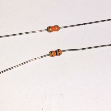
1 x 10K Resistor
1 x 33K Resistor
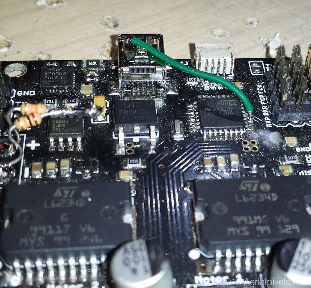
Solder one end of the 10k resistor to (-) Negative Battery Supply pad.|
Solder one end of the 33k resistor to (+) Positive battery Supply pad
Solder the 2 free end together
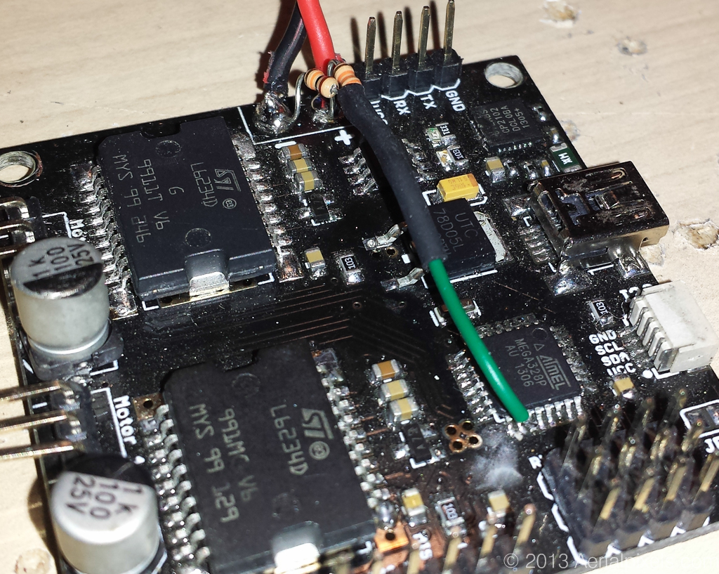
Solder a wire from pin number 19 of the 328 chip to the point where the 2 resistors are soldered together
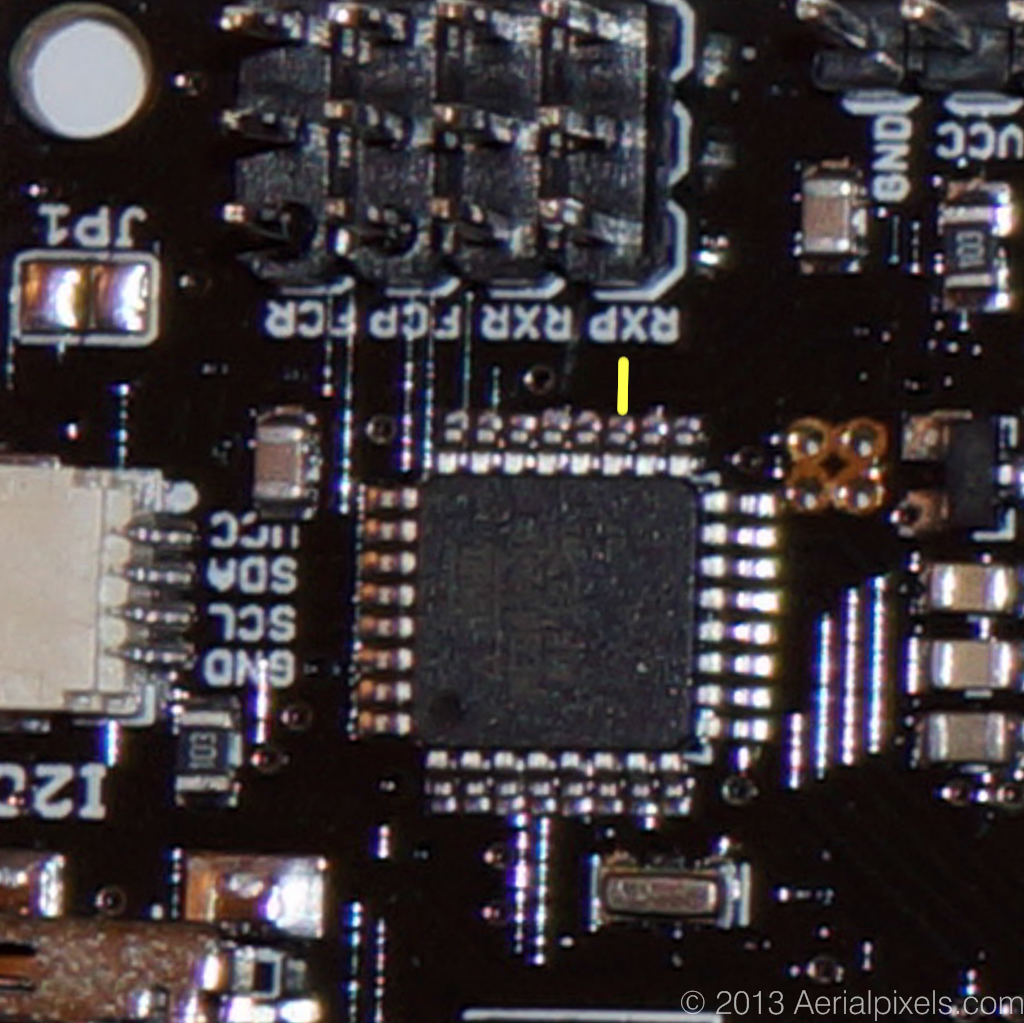
Location of PIN 19
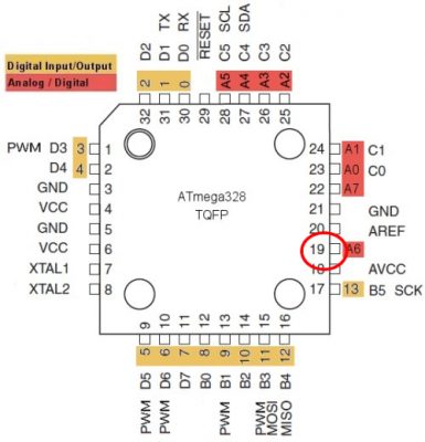
Location of PIN 19 shown with the yellow pointer
Completed view

So this compensates the PIDs as the voltage drops? Just making sure I understand. I was having this problem as my 4s voltage dropped under heavy load so I am using a 3A 12V regulator to drive my Alexmos and re-tuned at 12V. Wish I knew this earlier. I think 3A will suffice.
Yes you are correct. Vcc level is paramount for PID’s to work as tuned.